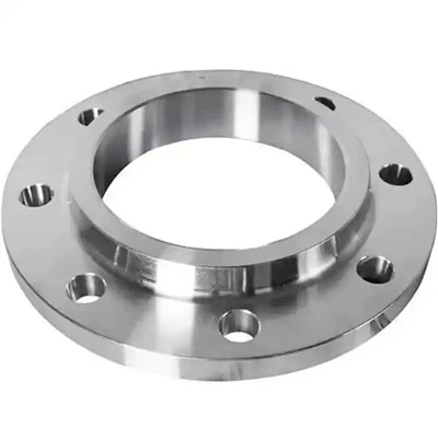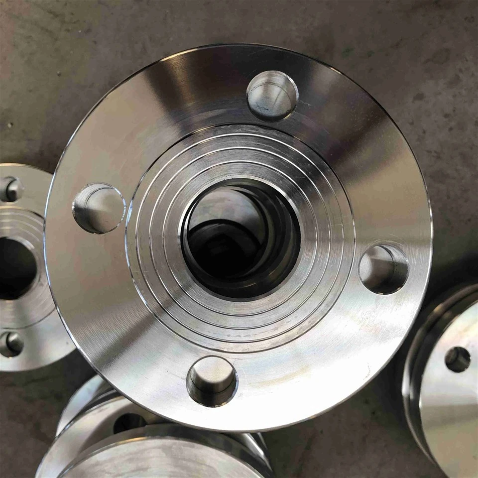

The slip on flanges class 150 are forged piping components manufactured to ASME B16.5, featuring a low-hub profile designed to slide over nominal pipe ends and secure through internal and external fillet welds.They are produced from forged carbon steel (ASTM A105/A105N, A350 LF2), stainless steel (ASTM A182 F304L/F316L), and alloy grades, with surface finishing options in black anti-rust paint, clear varnish, or hot-dip galvanizing.Available in sizes from NPS 1/2" through NPS 24" with Raised Face (RF) or Flat Face (FF) configurations, these flanges support full customization for exact pipe outside diameter tolerances, special bore IDs, and smooth or serrated face finishes.
Rated for a maximum cold working pressure of 285 psi (19.6 bar) at ambient temperatures and hydrostatically shell-tested at 450 psi (31 bar), this product provides a cost-effective connection for low-to-medium pressure fluid, gas, and plant utility systems.
Structural Characteristics & Low-Hub Geometry
Sliding Fit Internal Bore
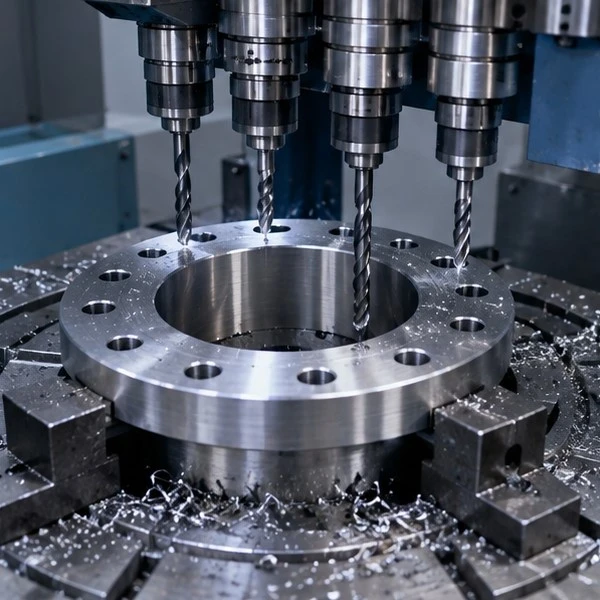
The inside diameter machined on slip on flanges class 150 features a controlled clearance (+0.8 mm / +0.03 in over nominal pipe OD), allowing field welders to slip the flange directly onto straight-cut pipe ends without end-bevel preparation.
Low-Mass Hub Profile
The Class 150 hub dimensions follow ASME B16.5 Table 9, utilizing a reduced neck height and lighter forged mass compared to Class 300 or Class 600 designs, which lowers fitting weight and reduces raw material costs for low-pressure piping.
Double Fillet Weld Attachment
Joint sealing and structural retention are completed through an outside fillet weld at the hub shoulder and an inside fillet weld near the pipe end, distributing mechanical shear stress across both weld throats.
Rapid Bolt Hole Alignment
Because the flange rotates freely over the pipe exterior prior to tack welding, technicians can quickly align bolt circles and straddle centerlines with mating equipment flanges.
Technical Specifications & Material Compliance
|
Engineering Parameter |
Standard Specification |
|
Manufacturing Standards |
ASME B16.5, ASME B16.47 Series A/B, DIN EN 1092-1 (Type 12 / PN 20), BS 4504 |
|
Nominal Size Range |
NPS 1/2" to NPS 24" (Standard ASME B16.5); NPS 26" to NPS 60" (ASME B16.47) |
|
Pressure Rating (Class 150) |
285 psig (19.6 bar) at -29°C to 38°C; Hydrostatic shell test pressure: 450 psig (31 bar) |
|
Forged Material Options |
Carbon Steel (ASTM A105/A105N, A350 LF2), Stainless (A182 F304/304L, F316/316L) |
|
Facing Configurations |
Raised Face (RF: 1.6 mm / 0.06 in height), Flat Face (FF) for cast equipment mating |
|
Gasket Contact Surface |
Serrated spiral or concentric finish: Ra 3.2–6.3 µm (125–250 AARH) per ASME B16.5 |
|
Certification & Traceability |
EN 10204 Type 3.1 MTR, 100% Dimensional & Visual Inspection, Hardness Verification |
Pressure-Temperature Derating & Gasket Loading
Thermal Pressure Derating Curve
Operating envelopes for slip on flanges class 150 follow ASME B16.5 Table 2-1.1. For standard A105 carbon steel, the maximum allowable working pressure steps down from 285 psi at 38°C (100°F) to 260 psi at 93°C (200°F), 200 psi at 204°C (400°F), and 140 psi at 315°C (600°F).
Bolt Circle & Clamp Mechanics
Class 150 bolt circles use 4 bolts on sizes NPS 1/2" through NPS 3", 8 bolts on NPS 4" through NPS 8", and 12 to 24 bolts on larger diameters (NPS 10" to 24"), delivering uniform gasket seating stress under standard ASTM A193 B7 bolting torques.
Gasket Material Compatibility
Designed for standard 1.5 mm (1/16 in) or 3.2 mm (1/8 in) non-metallic gaskets (EPDM, compressed aramid fiber, PTFE) and spiral wound gaskets with carbon steel outer centering rings (ASME B16.20).
Service Boundary Limits
Due to the fillet-welded hub transition, Class 150 slip-on flanges are rated for steady-state low-to-medium pressure piping. Systems subject to severe water hammer, heavy cyclic thermal shocks, or extreme bending moments should specify Class 300 or weld neck connections.
Standard Industrial Applications & Service Lines
Plant Utility & Cooling Systems
Forged slip on flanges class 150 serve as the standard connection fitting in raw water lines, cooling tower circulation, compressed air distribution, and low-pressure steam utility networks.
Atmospheric Storage & Transfer Lines
Installed across tank farm manifold headers, fuel loading racks, and offsite liquid transfer lines operating within Class 150 pressure boundaries.
HVAC & District Water Supply
Specified in municipal water treatment plants, commercial building central heating/cooling risers, and fire protection sprinkler distribution mains.
Low-Pressure Process & Exhaust Piping
Applied in flue gas desulfurization (FGD) ducts, low-pressure chemical drain lines, and atmospheric distillation overhead lines.
FAQ
Q: What is the maximum working pressure for a Class 150 carbon steel slip on flange across different temperatures?
A: Per ASME B16.5 Table 2-1.1 (Material Group 1.1 / ASTM A105), the maximum allowable working pressure is 285 psig (19.6 bar) from -29°C to 38°C (-20°F to 100°F). It derates to 260 psig at 93°C (200°F), 200 psig at 204°C (400°F), and 140 psig at 315°C (600°F). Standard hydrostatic shell test pressure is 450 psig (31 bar) at ambient temperature.
Q: Why are Class 150 slip on flanges not recommended for severe cyclic thermal services?
A: Slip on flanges have lower fatigue resistance than weld neck flanges because fillet welds create mechanical stress concentration notches at the hub transition. Under severe cyclic thermal expansion, heavy pressure surges, or rapid fluid hammer, stresses concentrate at the weld root. For severe cyclic or high-pulsation services, Class 300 or weld neck connections are specified.
Q: What is the required pipe setback distance before welding a Class 150 slip on flange?
A: Per ASME B31.3 Figure 328.5.2B, the pipe end must be inserted into the bore and set back from the gasket contact surface by a distance equal to the pipe wall thickness plus 1.6 mm (1/16 in), with a minimum setback of 1.6 mm. This gap prevents weld root burn-through from distorting the gasket seating face and accommodates thermal expansion during fillet welding.
Hot Tags: slip on flanges class 150, China slip on flanges class 150 manufacturers, suppliers, factory, 3 inch weld neck flange, 4 weld neck flange, carbon steel flange, high hub blind flange, metal flange, raised flange