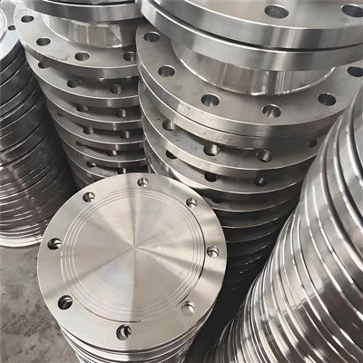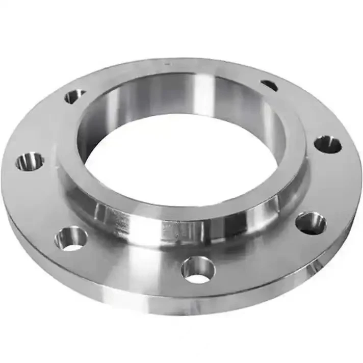
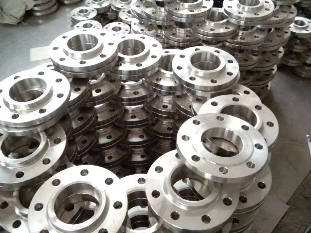
The reducing slip on flange is a one-piece forged fitting manufactured to ASME B16.5 Clause 6.8, integrating standard large-diameter outer dimensions and bolt circles with an undersized internal bore for direct in-line pipe transitions.It is available in forged carbon steel (ASTM A105N, A350 LF2), stainless steel (A182 F304/F316L), and alloy grades, with protective options including black anti-rust lacquer, transparent oil, or hot-dip galvanizing.
We supply outer sizes from NPS 2" to 24" (Class 150–900) stepped down to 1/2" pipe bores across RF, FF, and RTJ configurations, supporting complete customization for non-standard schedules, tailored reduction ratios, and specific facing finishes.Engineered for compact skid packages, pump nozzle tie-ins, and manifold assemblies, this fitting eliminates standalone pipe reducers and two circumferential butt welds, saving 60% in axial space while reducing fabrication labor and NDT inspection costs.
Key Features & Design Advantages
Integrated Pipe Size Reduction
Instead of welding a separate pipe reducer between two regular flanges, the reducing slip on flange provides direct size transition within a single forged fitting. This one-piece design simplifies piping layouts and reduces assembly steps.
Reinforced Hub Strength
Because the internal bore is smaller than that of a standard flange in the same pressure class, the hub wall remains thicker. This extra forged material provides higher structural rigidity around the pipe connection.
Standard Bolt Pattern Compatibility
The bolt circle, bolt holes, and outer dimensions match standard mating flanges, valves, or equipment nozzles, allowing easy integration into existing piping lines.
Double Fillet Weld Attachment
The flange is secured to the smaller pipe using both an internal and an external fillet weld, creating a tight seal and dependable mechanical strength for low-to-medium pressure systems.
Technical Specifications & Size Options
|
Specification Item |
Standard Range & Options |
|
Manufacturing Standards |
ASME B16.5 (Clause 6.8 for Reducing Flanges), ASME B16.47, MSS SP-51 |
|
Mating Outer Flange Sizes |
NPS 2" to NPS 24" (Class 150, Class 300, Class 600, Class 900) |
|
Reduced Inner Bore Sizes |
From 1/2" up to matching line requirements (Single-step and multi-step reductions) |
|
Available Materials |
Carbon Steel (ASTM A105/A105N, A350 LF2), Stainless Steel (ASTM A182 F304/F316L), Alloy Steel |
|
Sealing Face Options |
Raised Face (RF), Flat Face (FF for pumps/cast valves), Ring Type Joint (RTJ) |
|
Sealing Surface Finish |
Serrated spiral or concentric finish: 125–250 AARH (Ra 3.2–6.3 µm) |
|
Quality & Inspection |
Visual and dimensional checks, hardness testing, EN 10204 Type 3.1 Material Test Certificate |
Space Savings & Installation Benefits
Compact Installation Length: In tight spaces such as equipment skids and modular units, installing a reducing slip on flange cuts down the total face-to-face length by replacing bulky "flange + pipe nipple + reducer" combinations.
Fewer Field Welds & Lower Testing Costs: By removing the need for a separate reducer fitting, you eliminate two full circumferential butt welds. This lowers welding labor, reduces non-destructive testing (NDT/X-ray) requirements, and minimizes potential leak points.
Reduced Nozzle Load on Equipment: Shorter piping assemblies reduce cantilever weight and bending strain on sensitive pump and compressor connections.
Flow Performance Notes: The internal diameter changes in a direct step rather than a long conical taper. It is ideal for clean liquids, cooling lines, and general utility gases at standard flow rates.
Typical Applications & Use Cases
Pump & Compressor Connections
An integrated reducing slip on flange is commonly used for connecting process piping directly to smaller pump suction and discharge ports where linear rack space is limited.
Skid Manifolds & Valve Assemblies
Fitting smaller control valves, pressure regulators, or flowmeters into larger distribution lines with minimal spool length.
Tanks & Pressure Vessel Nozzles
Adapting large vessel openings (such as NPS 2" to 4") down to 1/2" or 3/4" connections for level gauges, sample lines, and drain valves.
Utility & Cooling Distribution Lines
Serving as branch connections in cooling water, plant air, and low-pressure steam headers where lines split into smaller feeds.
FAQ
Q: How are the dimensional standards of a reducing slip on flange determined under ASME B16.5?
A: Under ASME B16.5 Section 6.8 and Table 6, the flange outside diameter, thickness, bolt circle diameter, and bolt hole count match the larger nominal pipe size (e.g., NPS 4 Class 150), while the internal bore diameter is machined to match the outside diameter of the smaller pipe size (e.g., NPS 2). When the reduction ratio exceeds standard tabular limits, the fitting is machined directly from a blind flange forging without a hub.
Q: When should an engineer specify a reducing slip on flange instead of a concentric pipe reducer?
A: A reducing slip on flange is specified when axial space is constrained (saving 60% in linear spool length within pump manifolds and skid packages) and where eliminating two butt welds reduces shop fabrication hours and radiographic testing (RT) costs. For abrasive slurries or high-velocity turbulent lines (>4.5 m/s), a conical concentric reducer is preferred to minimize localized step erosion.
Q: Do reducing slip on flanges require custom bolt lengths or special bolt torque settings?
A: Bolt diameter, bolt count, and bolt circle remain identical to standard mating flanges of the larger nominal rating. Because the smaller bore leaves a thicker hub wall, standard stud bolt lengths for the outer flange class apply without modification. Bolt pre-loads follow standard ASME PCC-1 torque tables for the designated outer flange class.
Hot Tags: reducing slip on flange, China reducing slip on flange manufacturers, suppliers, factory, duct flange, flange with neck, plumbing flange, slip on flange pipe welding, slip on welding steel pipe flanges, stainless steel flange